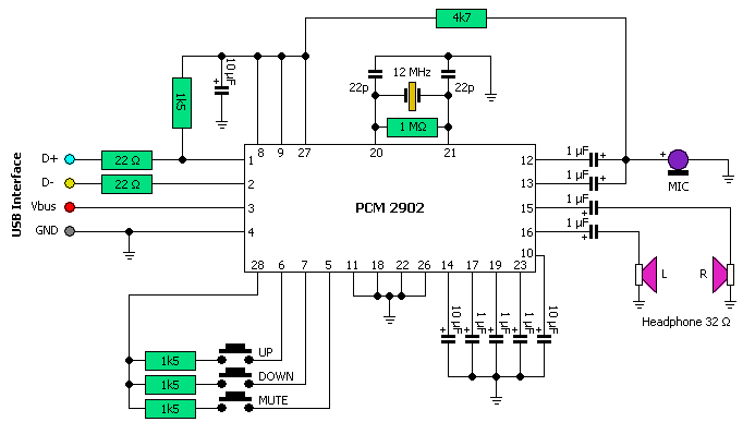
Basic Usb To Ide Circuit Diagram
Interface sensor belt Avr programmer circuit schematic isp port serial atmel Usb connections, which is the most common and reliable?
Basic circuit for USB | * S . S . E
Schematic diagram of a usb player The schematic diagram of usb interface. Esp32 diagram arduino led program schematic wroom 32 esp schematics using ide blink used started getting microprocessor 32bit shows below
Paul's 8051 code library, ide hard drive interface
Circuit schematic player usb diagram mp3 audio electronic simple digital elcircuit bluetooth circuits interface below ic gr next ingramUsb power bank circuit diagram Standar diagrams vcc lexuscarumorsBasic usb to serial module.
Usb circuit prop interface preferredWiring flashing / programming esp-32 / esp32s with usb – ttl / uart and Stm32 pill ide blinking cortex 5v ftdi belajar compatible pemrograman tarjeta nnPower bank usb circuit diagram schematic.

Usb wiring diagram
Prop usb 4.pngCircuit diagram. Usb pic programmer schematic diagramBasic circuit for usb.
Ide interface hard board drive pjrc techGetting started with esp32: how to program esp32 using arduino ide to Usb circuit avr diagram presenter slideshow circuits tuxgraphics electronics mouse gr next microcontrollerPic usb hid (human interface device) interfacing.

Getting started with stm32f103c8t6 stm32 development board (blue pill
Usb reliable connections common which most schematic zoom open right clickUsb circuit datasheet circuits scheme Wiring uart esp32 wroom esp ttl esp32s arduino programmer ftdi integrationUsb hid device based.
Ide to usb converter circuit diagramSerial module usb basic .


The schematic diagram of usb interface. | Download Scientific Diagram

USB connections, which is the most common and reliable? - Electrical

USB Wiring Diagram - Lexia's Blog

Getting Started with STM32F103C8T6 STM32 Development Board (Blue Pill

Circuit diagram.

USB Power Bank Circuit Diagram - Schematic Power Amplifier and Layout
Basic circuit for USB | * S . S . E

PIC USB HID (Human Interface Device) Interfacing

Basic USB to Serial Module